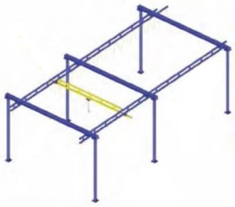
Free
Standing Work Station
|
||||||||
|
The safe, productive,
ergonomic solution for
overhead materials handling operations. |
Enclosed
Track Design Makes for Easy Movement and Long Life |
|||||||
 |
The
steel Work Station Crane System utilize enclosed track that is high in strength and low in weight. Major advantages: • Enclosed track cranes are up to three times easier to move than traditional bridge cranes. • The design virtually eliminates dirt and dust from the rolling surface, thus reducing wear on the wheels of the trolley and end trucks. • The smooth running surface means lower rolling resistance. • The low profile of the steel track allows the system to be installed where headroom is a problem. • The low track weight reduces the applied forces exerted on the supporting structure. • Long spans allow systems to be installed where support assemblies are infrequent (up to 30 feet with steel truss design). This reduces the possibility of the support columns interfering with the work cell layout. • Four distinct sizes of track -- 250, 500, 1000, and 2000 series -- enable you to keep bridge weights and costs to a minimum. |
|||||||
| Pricing
and Dimensional Specifications - Click a Load Capacity Link Here |
||||||||
|
||||||||
 |
||
 |
||
| Rigid
Runways Provide for Superior Positioning of Loads |
||||||||
 |
The
2° taper of the running flange helps to center the trolley in the track for smooth, effortless movement of trolleys and end trucks. |
|||||||
|
Work Station Bridge Cranes
are installed so that the |
||||||||
 |
||||||||
| What is meant by Rated Capacity? | ||||||||
| The
rated capacity is the live load that can be lifted by the crane system. The design load for the crane system is based on the rated capacity plus 15% for the weight of the hoist and trolley (capacity x 1.15) and an additional 25% for impact (capacity x 1.25) for a total design of capacity x 1.4 (Note, 25% impact factor is good for hoist speeds up to 50 f.p.m.). For example, a 1000 lb. crane allows you to pick up a 1000 lbs. load, provided the hoist weights 150 lbs. or less and the hoist speed is less than 50 feet per minute. |
TRUSSED STEEL TRACK: | |||||||
| Permits
longer spans which allows more flexibility in crane layout. |
||||||||
|
The trussed series uses the
plain steel track profile but is |
||||||||
| Design
load for deflection calculations is based on the rated capacity plus 15% for the weight of the hoist and trolley (capacity x 1.15). Under no conditions should the crane be loaded beyond it rated capacity. Work Station Cranes meet or exceed the ANSI B30.11 specifications for underhung bridge cranes. |
||||||||
| Mixed Capacity Bridge Crane Systems: | Easy to Install | ||||||
| Reduced
bridge dead weight equals better ergonomic solutions. |
Free
Standing Work Station Bridge Cranes can be installed on any normal 6" reinforced concrete floor. Each column is anchored by four bolts, thus eliminating the need for field welding. Support columns are designed to AISC specifications. If no movement of the support assemblies is required, then bracing to the building is recommended (not included). |
||||||
| Mixed-capacity
systems allow multiple lower capacity bridges to be used on higher capacity runways, provided the equivalent center loads (ECL) are verified at the factory to ensure that runways and hangers are not overloaded. For example, using mixed-capacity end trucks, four 500 lb. bridges (utilizing 500 series rail) can be hung from a 2000 lb. runway, allowing side-by- side use of all four bridges without overloading the system. By mixing bridges of various sizes and cap- acities, mixed-capacity systems offer reduced bridge dead weight, easier movement, and reduced cost. |
|||||||
| Modular Design | |||||||
| The
pre-engineered modular kit design permits easy expansion or relocation. The runway length can be increased by adding runway sections, free standing support assemblies and additional bridges as needed. |
|||||||
| Pricing
and Dimensional Specifications - Click a Load Capacity Link Here > |
|||||||
|
|||||||
|
Anatomy
of a Work Station Crane
|
||||||
 |
 |
|||||
| 1 | HOIST TROLLEYS | |||||
| Hoist
trolleys provide the connection between the lifting device and the monorail. The trolleys are designed for effortless movement along the track. The stamped body fits most rigid hook or eye lifting devices. |
||||||
| •
Wheels are tapered to match the 2° taper of the track. This reduces rolling resistance and wheel wear. Wheels contain ball bearings that are sealed and lubricated for life. • Trolleys are designed to operate in temperatures from +5° F to +200° F. • All trolleys meet or exceed the ANSI B30.11 specification for underhung bridge cranes. |
||||||
|
2
|
END TRUCKS | |||
| End
trucks provide the connection between the bridge and runways. They are designed for effortless movement along the runway. • Wheels are tapered to match the 2° taper of the track, which reduces rolling resistance and wheel wear. Wheels contain ball bearings that are sealed and lubricated for life. • Two horizontal wheels center the end truck within the runway which prevents binding of the bridge. As a result, the position of the load on the bridge has little effect on the amount of force needed to move the bridge along the runway. • Any slight runway track misalignment is taken up by the bridge floating in one end truck, while the other end truck is firmly clamped to the bridge. • All end trucks meet or exceed the ANSI B30.11 specification for underhung bridge cranes. |
||||
 |
||||
 |
||||
|
3
|
FESTOON GLIDES | |||
| Festoon
gliders are used to support flat cable along the monorail, and they are standard on monorails of 63 feet or less. No tools are required to attach the festooning to the gliders. |
||||
 |
||||
|
4
|
FESTOON TROLLEYS | |||
| Festoon
trolleys (optional) are used to support flat cable or air hose along the monorail. The trolleys have four wheels and a pivoting festoon saddle support. They are ideally suited for long runways (greater than 63 feet) or with round cable or air hose. With monorails greater than 63 feet or with an all aluminum system, festoon trolleys are standard. Special festoon trolleys for vacuum hose are also available. |
||||
 |
|||||
|
5
|
FESTOON CLAMPS | ||||
| Festoon
clamps anchor the festooning at the start of the monorail. They also prevent the festoon gliders from exiting the track and they can provide a redundant stop of the trolley. |
|||||
 |
|||||
|
6
|
END STOP BUMPERS | ||||
| High-impact
molded end stop bumpers are provided on all monorails, to prevent the trolley from exiting the track. The bumpers are bolted to the track to physically limit the travel of the trolley. |
|||||
 |
||||
|
7
|
UNIVERSAL BUMPERS | |||
| A
universal bumper can be used as a secondary end stop, either internally or externally. |
||||
|
8
|
STACK SECTIONS | |||
| A
stack section at one end of a monorail serves as an extension that allows festoon carriers to be stored on the end of the monorail without reducing hoist coverage. |
||||
 |
||||
|
9
|
FLAT CABLE AND/OR AIR HOSE | |||
| A
flat cable festooning system is included in all monorails. Plenty of cable is provided for 3 foot loops on the monorail. Optional air hose is also available and is supported by optional festoon trolleys. |
||||
| Optional
air hose is also available and is supported by optional festoon trolleys. Work Station Cranes can utilize optional conductor bar electrification, but this results in an increase up to 40% of the amount of effort required to move the system. |
||||
 |
10
|
HANGER ASSEMBLIES | ||
| Each
Work Station Bridge Crane is provided with the appropriate number of hanger assemblies, based on the number of support assemblies shown on the dimensional section. |
||||
| Hangers
for Trussed Steel Track Hangers for steel runways are included with each assembly as shown. The runways are flush mounted under the free standing support assemblies via spine clamp angles, B7 alloy threaded rods, and the appropriate hardware. |
||||
 |
|||
| SPLICE JOINTS FOR STEEL TRACK | |||
| A splice joint
is used to join track sections together and enable the installer to quickly and properly align the joined sections of track. Adjusting bolts are provided on the splice joint for leveling and aligning. |
|||
| Pricing and Dimensional Specifications - Click a Load Capacity Link Here | |||
|
 |
|||||||||||||||||||||||||||||||||||||||||||||||||||||||||||||||||||||||||||||||||||||||||||||||||||||
| L 1 = | MAXIMUM
SUPPORT ASSEMBLY CENTERLINE Maximum Support Assembly Centerline is con- sidered from the center of a support assembly to the center of the neighboring support assembly. |
|||||||||||||||||||||||||||||||||||||||||||||||||||||||||||||||||||||||||||||||||||||||||||||||||||||
| Note: | Anti-kick-up
end trucks* are required for the following: bridges with < 8' span (L4) and a bridge cantilever (L5) > 12" bridges with < 10' span (L4) and a bridge cantilever (L5) > 15" bridges with < 15' span (L4) and a bridge cantilever (L5) > 18" |
|||||||||||||||||||||||||||||||||||||||||||||||||||||||||||||||||||||||||||||||||||||||||||||||||||||
| L 2 = | SPLICE
JOINT CENTERLINE TO SUP- PORT ASSEMBLY CENTERLINE Splice Joint Centerline to Support Assembly Cen- terline is considered from center of a splice joint to the center of the nearest support assembly. |
|||||||||||||||||||||||||||||||||||||||||||||||||||||||||||||||||||||||||||||||||||||||||||||||||||||
|
**
|
||||||||||||||||||||||||||||||||||||||||||||||||||||||||||||||||||||||||||||||||||||||||||||||||||||||
| L 4 = |
BRIDGE SPAN |
|||||||||||||||||||||||||||||||||||||||||||||||||||||||||||||||||||||||||||||||||||||||||||||||||||||
| *
Anti-kick-up end trucks are not included as part of the standard crane kits. **2000# @ 10' span (L4) and bridge cantilever (L5) 15" need anti-kick-up end trucks. Consult us for information on bridges greater than 15' span (L4). |
||||||||||||||||||||||||||||||||||||||||||||||||||||||||||||||||||||||||||||||||||||||||||||||||||||||
| L 5 = | BRIDGE
CANTILEVER Bridge Cantilever is considered from the center- line of the runway to the end of the bridge (see table and notes). |
|||||||||||||||||||||||||||||||||||||||||||||||||||||||||||||||||||||||||||||||||||||||||||||||||||||
|
||||||||||||||||||||||||||||||||||||||||||||||||||||||||||||||||||||||||||||||||||||||||||||||||||||||
| L 9 = | MAXIMUM
RUNWAY CANTILEVER Runway Cantilever is considered from the center of the end support assembly to the end of the runway. |
|||||||||||||||||||||||||||||||||||||||||||||||||||||||||||||||||||||||||||||||||||||||||||||||||||||
|
|
Bridge Cranes,
Cranes, Free Standing Work Station Bridge Cranes, Free Standing Bridge
Cranes, Overhead Bridge Cranes, Hoist,
|