Back to Product Page
|
OVERHEAD
BRIDGE CRANE REMOTE CONTROL SYSTEMS
|
|
PATRIOT™
|
|
|
|
|
|
|
|
The
most affordable, high quality remote crane control
available from the Patriot® brand. 100% American
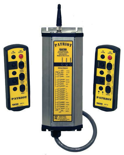
made and supported, the Patriot® is offered in four
models, all of which use Patriot’s proven Command
Pro® technology. All Patriot systems are shipped ready
to install with a six foot long wiring harness and include
our exclusive extruded aluminum receiver enclosure.
Best of all, the Patriot series transmitters come with a
One Year Unconditional Warranty! |
|
|
|
|
|
|
 |
|
|
|
|
|
 |
|
|
|
|
|
|
|
| HIGHLIGHTS |
|
|
|
|
|
|
|
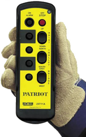
•
compact and extremely tough keypad operator control
• A rugged and reliable system means less downtime
• Superior factory support with an unconditional one-year
warranty
• Made entirely in the USA
|
|
|
|
|
|
|
|
|
|
|
|
|
HIGH-VALUE,
RELIABEL CRANE CONTROLS
|
|
|
|
 |
|
|
| See
below Prices for Configuration Sheets and Specifications |
|
|
|
|
FEATURES
|
|
|
|
•
Up to 15 Functions
• On/Alarm and Off/Stop Buttons
• Up to 3 Two-Step Discrete Rockers
• Up to 6 Push Buttons
• Optional Multiplex Selector
• LED for Operational Status
• Long-life disposable batteries |
|
•
1 Year Unconditional TX warranty
• TX Leather Holster & Strap Not Included
• Standard TX Labels Supplied
• 120 VAC Receivers
• NEMA 12 Enclosure
• No Transfer Switch on Receiver
• 10-foot Pigtail |
|
|
|
|
|
|
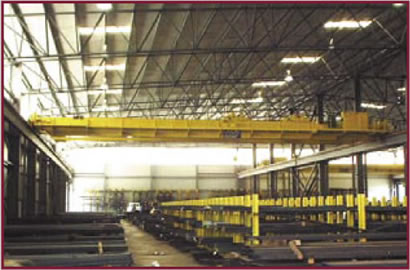
| APPLICATIONS |
The
systems are built to survive in aggressive industrial environments. |
|
|
|
|
|
|
|
•
Overhead Cranes
• Heavy Machinery
• Ship Loaders |
|
•
Metal Fabrication
• Amusement Parks
• Lifting Equipment |
|
|
|
|
|
|
|
| COMPLIANCE |
UL508
Electrical Safety |
|
|
|
|
|
|
|
|
 |
|
|
 |
|
Order
Online, by Phone, or by E-Mail |
|
|
|
~
Add items to your online shopping cart ~
Click the Model No. of the item
you wish to purchase.
|
|
|
|
Prices
|
|
Model No.
|
Description
|
Price
|
|
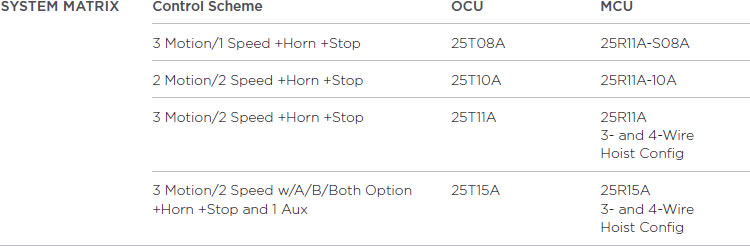
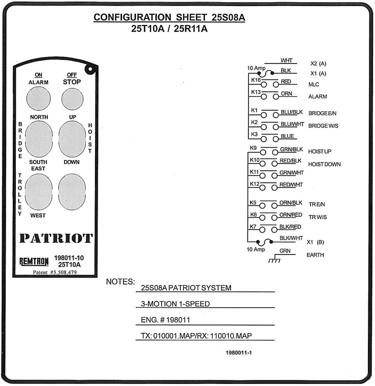
Three-Motion/One-Speed Cranes
|
|
|
25T10A Transmitter and 25R11A Receiver
|
$1,962.50
|
|
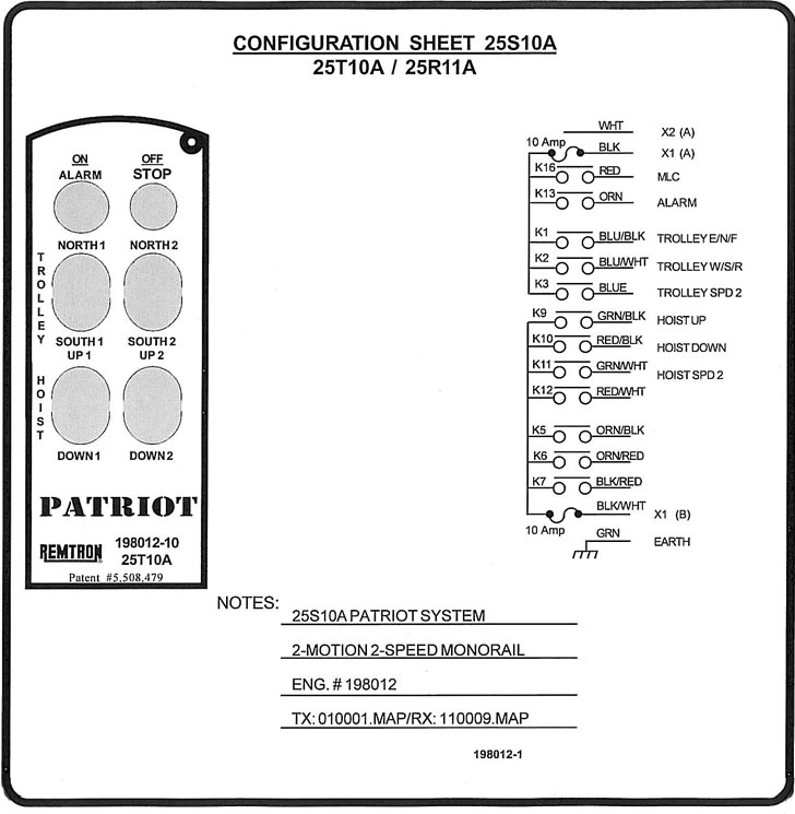
Two-Motion/Two-Speed Monorails (Not for use on Ramp
& Hold)
|
|
|
25T10A Transmitter and 25R11A Receiver
|
$2,087.50
|
|
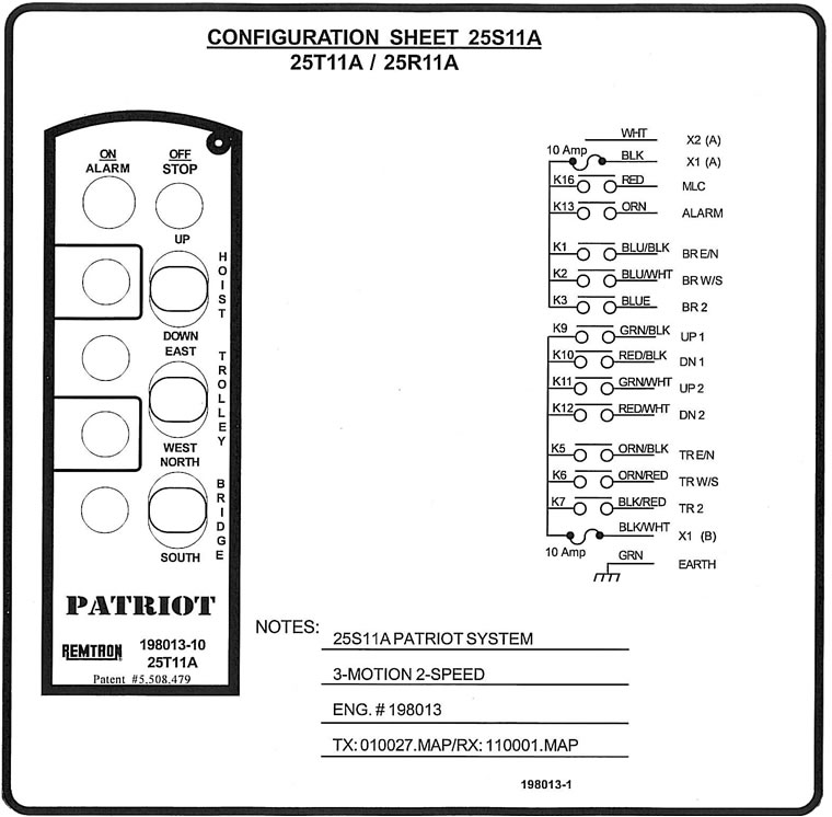
Three-Motion/Two-Speed Cranes
|
|
|
25T11A Transmitter and 25R11A Receiver Includes:
-Control for 3 or 4 wire hoist configuration
-Outputs for the M/L and Alarm
|
$2,487.50
|
|
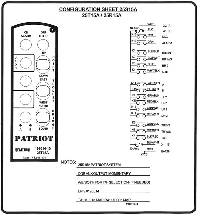
4 or 5 Motion/Two Speed Cranes W/ A/B/Both T/H Selector
|
|
|
25T15A Transmitter and 25R15A Receiver Includes:
- Control for 3 or 4 wire hoist configuration
- Outputs for the M/L and Alarm - A/B/Both software
for T/H selection
- One momentary auxiliary output
|
$3,125.00
|
|
Options
|
|
|
Additional 1 year Extended Warranty, Handheld Transmitter |
$250.00 |
|
Note:
The 25S15A system selects auxiliary T/H(s) using a P/B selector
and requires pilot relays. For spares and
aftermarket parts, please see below. ~ Spare transmitter price
at time of system order.
*Only available at time of original sale. |
|
|
TECHNICAL
DATA AND SPECIFICATIONS
|
|
|
|
|
|
|
| ELECTRONIC
DATA |
|
MECHANICAL
DATA |
Commands
See matrix on front
Digital circuitry Microprocessor technology
System addresses 16-bit, 65,535 unique addresses
Energy-saving mode Automatic shutdown
(15 minutes)
Supply voltage 2- AA batteries
Autonomy >130 hours typical |
|
|
|
|
|
|
OCU |
MCU |
|
Weight |
T10A
0.25 kg ( 9 oz) |
---
|
|
|
|
|
|
T11A/T15A
0. 28 kg (10 oz) |
|
|
|
|
|
|
Dimensions
L x W x H |
T10A
7 x 16.5 x 2.5 cm
(2.8 x 6.5 x 1 in) |
25.4x12.7x6.4
cm
(10 x 5 x 2.5) |
|
|
|
| OPERATION
AND INDICATION |
|
|
|
|
|
|
|
|
|
|
|
|
|
| Actuators |
Up
to 3 dual step rocker switches,
horn, stop, Aux and A/B/both |
|
|
T15A
7 x 20.5 x 2.5 cm
(2.8 x 8.1 x 1 in) |
|
|
|
|
|
|
|
|
|
|
| LED
|
1
status LED for active, low battery |
|
|
|
|
|
|
|
|
|
|
Housing |
High-impact,
fiber-reinforced
nylon |
Aluminum |
| RF |
|
|
|
|
|
|
|
|
|
Frequency
range |
902-927
MHz
85 RF channels |
|
|
|
|
|
|
|
|
|
IP67,
suitable for
outdoor use |
IP52,
suitable for
indoor use |
|
|
|
|
| Transmitter
output power 1mW license exempt |
|
|
|
|
|
|
| Modulation |
Packet
Mode, FM |
|
|
|
|
|
|
|
Operating
temperature |
-29°
to +71° C |
(-20°
to +160° F) |
|
|
|
| RF
channel spacing 300 KHz |
|
|
|
|
|
|
|
|
|
| Antenna |
Internal |
|
|
|
|
|
|
|
|
Vibration
and
shock |
Vibration/impact
and drop
tested to 1m on concrete |
|
|
|
| FCC
ID |
T10A
style
EGT810TX (25T10A) |
|
|
|
|
|
|
|
|
|
|
ACCESSORIES |
|
T18A
style
ECT818TX (25T11A, 25T15A) |
|
|
|
Batteries |
2-
standard AA |
|
|
|
|
|
|
|
3-motion/1-speed
25S08 - 25T10A Transmitter and 25R11A Receiver
|
|
 |
|
|
2-motion/2-speed
25S10 - 25T10A Transmitter and 25R11A Receiver
|
 |
|
|
3-motion/2-speed
Cranes 25S11A - 25T11A Transmitter and 25R11A Receiver
|
 |
|
|
4
or 5-motion/2-speed Cranes W/ A/B/Both T/H Selector 25S15A
-
25T15A Transmitter and 25R15A Receiver
|
 |
|
Tech
Note
IP Ratings Explained
|
|
The
IP Code defined in international standard IEC 60529 classifies
the level of protection that electrical appliances
provide against the intrusion of solid objects or dust, accidental
contact, and water. It consists of the letters IP (for
"international protection rating"[1], sometimes also
interpreted as "ingress protection rating") followed
by two digits
and an optional letter.
The digits indicate conformity with the conditions summarized
in the tables below. Where there is no protection rating
with regard to one of the criteria, the digit is replaced with
the letter X.
For example, an electrical socket rated IP22 is protected against
insertion of fingers and will not be damaged or
become unsafe during a specified test in which it is exposed
to vertically or nearly vertically dripping water. IP22 or
IP2X are typical minimum requirements for the design of electrical
accessories for in-door use. The standard aims to
provide users more detailed information than vague marketing
terms such as "waterproof".
Patriot transmitters are IP66/67 rated. Below is a break down
of what IP66/67 is in relation to our
products.
First digit:
The first digit indicates the level of protection that the enclosure
provides against access to hazardous parts (e.g.,
electrical conductors, moving parts) and the ingress of solid
foreign objects. |
|
|
Level
|
Object protected against
|
Effective against
|
|
6
|
dust tight
|
No ingress of dust; complete protection against contact
|
|
|
Second
digit:
Protection of the equipment inside the enclosure against harmful
ingress of water. |
|
|
Level
|
Object protected against
|
Details
|
|
6
|
powerful water jets
|
Water projected in powerful jets against the enclosure
from any direction shall have no harmful effects.
|
|
7
|
immersion up to 1 m
|
Ingress of water in harmful quantity shall not be possible
when the enclosure is immersed in water under defined
conditions of pressure and time (up to 1 m of submersion).
|
|
IP
codes are similar to NEMA ratings. Equivalent NEMA ratings for
Patriot products with IP ratings:
NEMA 4 Water Tight & Dust Tight - Indoors/Outdoors
Type 4 enclosures are intended for general purpose indoor or
outdoor use primarily to provide a degree of protection
against windblown dust and rain, splashing water, and hose directed
water; and to be undamaged by the formation
of ice on the enclosure.
NEMA 6 Submersible, Water Tight, Dust Tight, & Ice/Sleet
Resistant - Indoors/Outdoors
Type 6 enclosures are intended for general purpose indoor or
outdoor use primarily to provide a degree of protection
against the entry of water during temporary submersion at a
limited depth; and to be undamaged by the formation of
ice on the enclosure. |
|
|
Technical
Note
Infrared Wireless Control
|
|
Infrared
(IR) has advantages and disadvantages for the use in remote
control. Infrared radiation is electromagnetic
radiation whose wavelengths are greater than those of visible
light but shorter than those of microwaves. In its most
familiar form, it is radiated heat which can be sensed by our
skin, yet cannot be seen by our eyes. All objects, what-
ever their temperature, emit infrared radiation. Like light
and unlike radio frequency (RF), IR is very directional and
is usually focused into a beam for best propagation. RF propagates
in all directions depending on the polarization of
the antenna and, especially at lower frequencies, can “bend”
around objects. The primary advantages of using IR in
remote control are: 1) no requirement for licensing or FCC certification
for use in license free bands, 2) relatively
low cost and, 3) safety restrictions that require the user to
be close to the receiver (usually less than 150 feet) and
in direct sight of the receiver. The disadvantages especially
over RF control systems include the following;
1. Directionality – At moderate distance, IR systems
require an operator to “aim” the hand held unit in
the direction
of the receptor. If on a crane, this is toward the bridge and
upward. The most significant operating problem
introduced is the fact that an operator must split his attention
between thinking of aiming constantly, verses, thinking
of moving the object involved.
2. Range – IR has very limited reliable range compared
to RF. IR tends to become intermittent at distances over
100 feet.
3. Sun Light – The IR component of the sun can interfere
with the IR signal. The receiver must be shaded from
the sun. In outdoor use the receiver must be installed to avoid
direct or reflected exposure from the sun. This is
particularly difficult at dawn and dusk and in very bright and
reflective environments.
4. Weather – IR is attenuated by dust, smoke, rain
and fog that will substantially reduce operating range. The
receiver lens must be frequently cleaned and protected from
rain, frost and ice to avoid further attenuation of the
signal.
5. Cluttered Work Environments – IR requires line-of-sight
from the transmitter to the receiver unlike RF.
Operators cannot control the equipment if vehicles and other
obstructions are between the transmitter and receiver.
6. Emergency Stop Response – In an emergency, the
operator must acquire the receiver before sending an
emergency stop command which delays shutting down equipment.
RF is almost instantaneous.
7. Safety Link – RF can maintain a constant link
from the transmitter to the controlled equipment (“maintained
link”) and automatically shutdown the equipment if the
transmitter fails or the batteries fail. Normal IR systems are
not capable of a “maintained link” mode and will continue
last command if the transmitter fails.
8. Night and Low Visibility Operations – Operators
have difficulty acquiring the receiver if the receiver location
is hard to locate.
9. Interference – There can be interference noise
that is disruptive to IR signals, some common sources are
lighting systems, heaters, and especially strobe lights used
on mobile vehicles. |
|
|
Technical
Note
Intrinsically Safe
|
|
Patriot
provides specially produced versions of selected models of our
products for use in hazardous environments.
These products are qualified as “intrinsically safe.”
What does that mean? Extra safety is required in environments
that include flammable gases, vapors, liquids, or dust. For
electronic equipment, the requirement is to eliminate any
point in the electronics that could be an ignition source. Depending
on the nature of the combustible environment, the
ignition source must be kept well beneath the combustible initiation
temperature of gas and dust in the environment.
Gases such as propane, and dust such as metals, coal, and grain,
have their own combustion temperatures. In some
highly combustible environments, we also can seal the electronics
in enclosures that contain combustion and prevent
it from igniting the local environment. Patriot defines “intrinsically
safe” in terms of Underwriters Laboratories (UL)
standards. Depending on the model, Patriot’s intrinsically
safe products are rated UL Class I, Division 1 and Groups
C and D; Class II, Division 1 and Groups E, F and G; and temperature
code T3.
• Class – Class I includes environments of
flammable gases, vapors, or liquids. Class II includes combustible
dust.
• Division 1 – This is the most stringent division
of either class. It covers situations where ignitable concentrations
of
flammable gases, vapor, or liquids (Class I) and combustible
dust (Class II) can exist all of the time or some of the
time under normal operating conditions.
• Groups – This specifies the type of flammable
substance in the hazardous environment. We are qualified in
five
groups: C (ethylene), D (propane), E (metals), F (coal), and
G (grains).
• T3 – This is a temperature code and rates
the equipment for environments of less than 200 degrees C.
Patriot uses the Intrinsically safe (2-fault) method as defined
in UL 913 (US) and CSA-157 (Canada) to achieve
this level of safety. These standards specify the design and
constructional requirements and test procedures for
equipment and parts of equipment intended for use in hazardous
locations and also for associated equipment intended
for use in safe locations. Each product that is rated carries
a unique label that specifics the rating, operational limits,
and instructions for maintaining the rating. Patriot’s
intrinsically safe processes are inspected quarterly by ETL
to
maintain our listing. |
|
|
Technical
Note
Battery Life
|
|
|
Some
operators have experience with transmitters that only last
for one work shift or about 10 hours and then require
recharging. Remtron’s transmitters last over 130 hours
of operation, depending on the model. That typically means
months of operation without being interrupted by a dead battery.
Long battery life makes a big difference in how you
operate and whether you need a rechargeable unit or can use
standard, off-the-shelf AA batteries.
Why do Patriot transmitters last so much longer than other
wireless transmitters? The secret is in the design.
Patriot transmitters are designed to be very frugal with the
available battery power. We use the following three
design techniques to greatly extend battery life:
• Efficient “Packet Mode” Transmission -
Transmitting is the largest drain on battery power. Our Command
Pro
transmitters operate in the 900 MHz band, where wideband operation
is feasible. Many competitors operate in the
400 MHz band or lower, where narrow-band transmission is required
to get the needed operating range. Operating
wideband allows a lot of data to be sent in a very short time.
This in turn means that “packet mode” transmission
can
be used to send data in a short burst. Then the transmitter
turns off until a new data packet is to be sent. Furthermore,
using a data compression scheme that greatly decreases the
transmitted bytes necessary to convey the necessary
information further reduces transmission time. A transmitter
that is turned on only for short periods of time requires
less power to transmit data. Most of our competitors operate
in a narrow band that requires almost continuous
transmission to get the data sent.
• Circuit Design Efficiency - Our transmitter
circuits are designed to be very efficient. The microprocessor
is used
sparingly and the transmitter is powered on only when sending
data. Further, if no new data needs to be sent (no
change in command switch positions), the transmitter duty
cycle is further reduced to the minimum that will safely
keep the system alive.
• Smart Battery Management - A battery power
converter is used so that the maximum amount of power can
be
withdrawn from each cell before its useful life is expended.
If a linear regulator is used to derive power from a
battery, up to 70% of the available energy in the battery
may be wasted. The power converter allows about 92%
of the power to be withdrawn.
Our Command Pro transmitters boast the longest battery life
in the industry. It was a goal during the design of
the Command Pro series to minimize the battery issues. Most
industrial remote controls require rechargeable
batteries, with their inherent problems, or require the purchase
of expensive specialized batteries from the manu-
facturer. In most cases, the batteries do not have very good
battery life. For the convenience of our customers,
Patriot designs its transmitters to use commonly available
AA cells. Our transmitters also accept rechargeable
AA batteries.
|
|
|
Technical
Note
Safe-T-Range™ - Controlled Range System
|
|
With
the advent of lower-cost wireless control systems for material
handling equipment, end users are becoming
increasingly aware of the potential for cranes to be operated
from unsafe distances. Today, most wireless remote
control manufacturers are offering their equipment on high frequency,
unlicensed bands that don’t require the
complicated licensing procedures of the past. With higher frequencies
comes the ability to operate a crane from a
distance of 300 to 1000 feet, which has caused some companies
to search for a solution to this safety concern. An
increasing number of companies’ industrial safety departments
are requiring range-limited controls for the safe
operation of their cranes, machinery, and other material handling
equipment. New solutions have been developed
that offer different ways of controlling the distance at which
the operator can operate the crane. The following are
a few of the techniques now available:
Infrared Control – Infrared control is commonly
used in household consumer items such as remote-controlled TVs,
VCRs, and stereo equipment. With infrared control, in order
to maintain control, the operator must keep in constant
contact with the crane by physically pointing the transmitter
at one or more infrared eyes on the crane. While this is
effective, infrared control still has long-range capabilities,
and the requirement to continuously point the transmitter
at the crane is often seen as a safety concern in itself. Infrared
control is also susceptible to plant dust and bright light
such as sunshine, which can interrupt signals and cause crane
movement to be stopped intermittently.
Infrared Start/RF (Radio Frequency) Control –
Controlling the range is also popular in Europe, where a tech-
nique called Infrared Start/RF (Radio Frequency) Control is
used. This technology uses an infrared transmitter and
receiver to start the crane main line contactor. Once the crane
is started, long-range radio frequency is then used to
control the crane motions. While this is believed to be a better
way of controlling a crane, limitations still exist.
Specifically, the tendency is for the operator to start the
crane in close proximity to it but then operate it at a much
farther distance, which defeats the purpose of keeping the operator
close to the crane at all times. The shortcomings
of infrared are again an issue with this type of system.
RF Range Control – The industry has shown that
radio frequency control is the preferred means of controlling
a crane and other material handling devices. RF is able to transmit
“around corners” and is free from the issues of
dirt or other airborne particles. However, with the very low
power of today’s unlicensed transmitters and the very
high frequencies that are being used comes a very long-range
signal that is difficult to control. But with today’s
microprocessor technology, manufacturers are able to manage
these RF signals to the end benefit of the operator
and their safety.
We offer an RF-controlled range system called Safe-T-Range™
that is not affected by modern automation
devices like Variable Frequency Drives (VFDs) or electronic
discharge machines commonly used in manufacturing
processes. The system can be custom-adjusted to the end user’s
range requirements, usually in the 30 to 100 ft.
range. The receiver monitors the power of the signal received
from the transmitter to determine the distance
between the operator and the equipment. The receiver may be
programmed to allow an operator to leave his “safety
circle” only for a short time period before he must return
to the safety zone. An indicator light or horn tells the operator
he is out of range and must return to his “safety circle”
of operation. If he does not return, the crane is brought to
a
safe stop. The end user can decide which functions he wants
to range control. For example, an operator may need
controlled range on the Hoist and Trolley but need a long range
on his bridge motion for calling the crane from the
end of a long bay. Of course, all safety functions may remain
enabled even if all other functions of the crane are
range-inhibited. |
|
|
Command
Pro Technical Note
Safety of Operation
|
|
Safety
is a special requirement of industrial wireless control systems.
Other wireless systems such as cellular phones,
car keyless locks, pagers, and even garage door openers don’t
have the safety concerns that face the wireless
operation of cranes or construction equipment. The design of
industrial wireless controls must have additional features
that reduce the probability of injury to operators and damage
to equipment or material. Our Command Pro
systems are designed specifically for this use and have the
following features that address each potential hazard:
• False Command Prevention – Wireless control
receivers must be designed to accept only valid commands,
and those valid commands must come from only one authorized
transmitter. Spurious signals from any other RF
energy source should not be misinterpreted as a command. Nor
should the receivers accept commands from any
other transmitter except the one that is registered and in control
of the equipment. We developed a very
unique design that is solely for controlling equipment and for
the reception of the Patriot specially formatted
signals in an industrial environment. Each command or packet
is subjected to error checking using Cyclic
Redundancy Codes (CRC) to prevent false commands. More than
64,000 unique address codes assigned to 82
frequencies are available using Patriot’s 16-bit address
code. This results in over 5 million unique identifiers.
For the transmitter to work, the unique identifier must be registered
with the receiver.
• Inadvertent Command Prevention – The
transmitter should not transmit a command unless the operator
makes a purposeful action to issue a command. Patriot protects
the controls during operation from inadvertent
commands by using a protective ridge around the unit. Critical
commands such as load release are protected by
requiring the operator to press two rocker switches simultaneously
and hold them for a couple of seconds. After
that time interval, the receiver implements the command. For
further protection, the unit “times out” when not
being
used and must be turned back on to activate the controls. Time-outs
may be set very short if a push-to-operate
(PTO) control must be pressed for each command. For special
concerns, Patriot provides a Safety-T-RangeTM
feature that limits the distance from the receiver at which
the operator can issue commands to the system.
• Emergency Stop Override – In the event
of an emergency, there must be a simple and readily accessible
command that will take precedence over all other communications,
stop the controlled equipment, and place the
equipment in a safe mode. Patriot provides an ESTOP button on
all Command Pro transmitters. The ESTOP
overrides all commands and has priority communication to the
receiver. Once received, the ESTOP command
triggers the receiver’s safety circuit to implement a three-step
shutdown procedure. The first step opens the motor
relays and stops movement of the equipment.
• Interrupted Transmission Failsafe –
In the event that the receiver loses the command signal from
the
transmitter, the receiver must take action to place the controlled
equipment in a safe mode. Patriot uses a
continuously transmitting protocol (maintained link) with the
receiver that includes a failsafe watchdog timer. If
the receiver does not receive a valid command in less than 60
milliseconds, it goes into shutdown mode.
Shutdown mode is programmed to go through three phases that
safely bring the equipment into a safe state of
operation.
• Receiver Failsafe - In the event the receiver’s
electronics fail or lose power, the relays that control the
equipment must fail to a safe mode of operation. Patriot has
a special safety circuit in each receiver that
automatically shuts down operations if the microprocessor fails
or if power is lost to the receiver. The relays
themselves are designed to fail to the open position, which
effectively disrupts the commands and halts
operation.
Our customers include major amusement parks and industrial plants
that depend on
Patriot systems as their primary emergency shutdown system. |
|
|
Technical
Note
Spread Spectrum
|
|
Patriot does not use spread spectrum techniques in its design.
Why not? Spread spectrum is the technique of
transmitting messages by spreading the transmitted energy across
a frequency band. It was first used by the military
to defeat attempts by the enemy to jam our transmissions or
intercept messages.
The enemy would try to jam a transmission by scanning a frequency
band, identifying a target transmitter, and then
transmitting at the same frequency to interfere with the receivers.
By spreading the energy, the transmitted signal was
difficult to detect. The wireless communications industry was
interested in finding other uses for this clever technique.
Proponents of spread spectrum reasoned that by using the technique,
more users could be accommodated in the
same frequency bandwidth. Although this was a controversial
argument, it nevertheless convinced some developers
to use spread spectrum in their equipment designs.
Would spread spectrum techniques improve the performance of
wireless control systems? Not for the type of
operations required by our customers. First, wireless control
applications do not have the operational uses that
would benefit from using spread spectrum techniques. There are
not hundreds of units in the same geographical
location competing for access. Second, spread spectrum does
not improve performance over current wireless
control systems. For controlling equipment at ranges less than
1,000 feet, spread spectrum does not perform
better than normal packet communications at 900 MHz. That is
because the packet communications protocols
implemented by Patriot are effective in reliably delivering
packets and defeating interference in this frequency
band. This has been demonstrated repeatedly over years of experience
in real operational environments.
The one advantage spread spectrum does have turns into a disadvantage
in practical operation. The FCC permits
transmission at a higher power when in a spread spectrum mode.
By taking advantage of this FCC ruling, spread
spectrum systems can command equipment well beyond 1,000 feet.
However, this distance is also well beyond the
safe operational range for controlling equipment, and the capability
to operate at such a distance introduces an
additional safety hazard in operations. Patriot designed its
wireless control systems to meet the specific needs of
the industry and its customers with a special emphasis on safety.
Why not use spread spectrum for whatever additional value it
may offer, even if that value is marginal? With any
additional complexity, there are penalties. The use of spread
spectrum increases the power drain on batteries and
shortens the time between battery replacement or recharge. More
complex transmission algorithms also complicate
diagnostics. It is harder to determine the cause of problems
with equipment with spread spectrum algorithms. To
get the full benefit of frequency hopping spread spectrum technology,
the implementation must use a long sequence
of channels. The longer the sequence, the longer it takes for
the receiver to acquire or lock on to the transmitter
before it can transmit data. This not only delays operation
when the units are first turned on, but it also further
reduces the opportunity to decrease power consumption in the
transmitters by permitting frequent time-outs to
extend the operating life of the battery.
Our approach is to design for the intended use of the system,
not for the available technology.
Our equipment is fully capable of implementing spread spectrum
algorithms if and when our
customers need their unique benefits. |
|
|
Command
Pro Technical Note
Operating Reliability
|
|
Some
equipment operators have experienced “dropouts,” or
short periods in which the transmitters don’t work.
It is an annoying problem, but it also can be a dangerous one
if you are relying on the wireless control system to
keep equipment under control. Dropouts occur for a number of
reasons. They happen most often because the
operating frequency band chosen is noisy with interference,
the communications protocol was not designed to
handle unexpected interference from other sources of RF energy,
or the physical terrain causes a blockage.
The Patriot system was designed to minimize dropouts. We did
that by selecting the most appropriate frequency
band permitted by the FCC for license-free operation and then
designing a protocol and electronics that took full
advantage of the bandwidth to reliably deliver commands.
At 900 MHz, we operate well above the frequency of RF noise
generated by electrical equipment that is one
source of interference. But 900 MHz is still low enough to permit
some “bending” of our transmission around
physical obstructions. The following are key features of our
design that help further protect against dropouts:
• Bandwidth – Patriot Command Pro transmitters
operate in the 900 MHz band, where wide-band operation
is permitted. Many competitors operate in the 400 MHz band or
at lower frequencies where only narrow-band
transmissions using limited power are permitted. Bandwidth determines
how quickly data may be transmitted. The
narrower the bandwidth, the longer it takes to transmit the
required data to issue a command to the equipment. By
organizing the data into quick transmission bursts, we have
decreased the probability of disruption by interference
and increased the probability of successful reception. That
is, we transmit more redundant packets, which reduces
the probability of a noticeable dropout.
• Power – Our transmitters are designed
for the maximum power allowed by the FCC for use on the 900
MHz
band. The power authorized for fixed-spectrum transmissions
is 1000 times greater than the power level authorized
for other bands commonly used for license-free operation. The
higher power permitted by the FCC at 900 MHz
not only substantially increases the range of the transmitters,
but also overpowers interfering RF energy. A strong
signal at 900 MHz is like a strong FM station on your car radio.
It will be received loud and clear even if there are
weak signals present from any other source.
• Decoding – We have developed our own
specialized algorithms to decode commands from our transmitters.
These algorithms are designed to ignore interfering signals
and to frequently retransmit messages in order to increase
the probability of successfully communicating. Our special coding
and signal processing is specifically designed for
control of apparatus over radio waves without noticeable dropouts.
• Antenna Polarization – For especially
noisy RF environments, we have developed a specialized antenna
that
is designed to ignore common sources of interference. Most interference
is vertically polarized. Our transmissions
are horizontally polarized. By designing an antenna that is
horizontally polarized, the effectiveness of the power of
interfering RF energy is greatly diminished. |
|
|
Technical
Note
Controller Area Network (CAN)
|
|
|
|
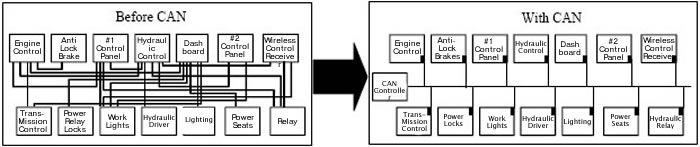
The
Controller Area Network (CAN) bus is designed for communication
between microcontrollers. In an auto-
motive environment, it is used to exchange information between
onboard Electronic Control Units (ECUs) such as
the Engine Management System, transmission, instrument packs,
and body electronics. The German company
Robert Bosch GmbH originally developed CAN for the automotive
industry during the late 1980s. Its motivation
for the development of CAN was to provide a solution to the
problem of the enormous and constantly growing
wiring harness required for inter-ECU communication in modern
vehicles. The company’s solution was to design a
single network bus to which all the on-board peripherals could
be attached. In 1993, CAN became ISO 11898
(the standard for high-speed applications) and ISO 11519 (the
standard for lower-speed applications). It is a multi-
master serial communications bus whose basic design specification
called for high speed, high noiseimmunity, and
error-detection features. |
|
|
|
|
 |
|
|
|
|
|
The CAN
communications protocol specifies the method by which data
is passed between communicating devices
on a CAN bus. It is the basic protocol (the first two layers
of the sevenlayer ISO Open System Interconnection
model) that permits the orderly transfer of messages in the
data bus. The transfer is managed by a CAN controller
that makes sure all network members have a chance to participate
and resolves any conflicts. To turn the messages
into useful information, a higher-order protocol (the seventh,
or Applications, layer) is also needed. The Application
layer protocols can be proprietary schemes developed by individual
CAN users or one of the emerging standards
used within particular industries. Common application layer
standards are DeviceNet, CANOpen, CAL, and SDS.
DeviceNet is especially suited to the networking of Programmable
Logic Controllers (PLCs) and intelligent sensors
and actuators. The application layer protocols also can provide
centralized diagnostics to permit quick isolation
of problems occurring in any node of the network. That is
a major advantage in the development
and maintenance of complex automotive systems.
The CAN Receiver (RCAN) supports the basic CAN protocol as
well as some of the application layer standard
protocols. Each manufacturer usually implements these protocols
in a slightly different manner in its equipment.
RCAN can be programmed to meet the specific requirements of
each. By interfacing through the CAN bus with
existing relays and drivers, the cost of duplicating these
devices in RCAN is avoided. This greatly reduces the
cost and complexity of adding wireless remote control to an
automotive-type system.
|
|
|
|
|
Technical
Note
THEORY OF OPERATION
|
|
The
Patriot Command Pro® equipment operates in the range from
902 to 928 Megahertz (MHz). A wavelength
at our frequency is 12.9 inches. The 400 MHz band used by most
other manufacturers has a wavelength of
29 inches. Like light, 900 MHz radio signals will pass through
glass and plastics, and will reflect off of walls,
buildings, and metal structures. Unlike light, 900 MHz radio
signals will penetrate all plastics, including those that
you cannot see through, thin-gauge steel, dry wood, dry concrete,
plasterboard, fog, and rain. Trees, earth, water,
people, aluminum, copper, and some window tints will not pass
our signals.
Antennas convert radio signals into radio waves and convert
radio waves back into radio signals. They can send
and receive in all directions or in a single direction, depending
on their design. An omnidirectional antenna is like a
light bulb, and a directional antenna is like a flashlight.
Metal objects reflect radio waves, just as a mirror next to
a
light bulb will reflect light. Metal objects near an antenna
alter the intended pattern of an antenna by either shading
or reflecting signals. Our standard antennas “see”
equally well in all directions. We have other antennas that
will
“see” further in one direction for special applications.
Our transmitters and receivers are designed to have more than
a 2.5-mile operating range in “free space” (an unobstructed
view). Our systems are range-tested to 600 feet, and we
guarantee 300-foot performance. The extra signal strength provides
a large margin, which allows for reliable
operation in the presence of objects that can reflect or absorb
radio signals.
The 902 to 928 MHz spectrum accommodates many license-free users
and is set aside by the FCC as an ISM Band
(Industrial, Scientific, and Medical). We have the ability to
change frequencies in this band and have 85 different
channels that we can assign to our transmitter and receiver.
The actual frequency is coded into the receiver and
transmitter at the factory but may be changed to one of the
other 84 channels in the field. Other devices in this
band include wireless phones, computer data links, and inventory
equipment. As a condition of using this band, we
must accept and handle interference from other users. The 900
MHz band has worked well for most users, and not
being burdened with licensing regulations is always desirable.
The FCC has allowed 50,000 microvolts per meter
field strength on this band, which is 250 times higher than
other unlicensed frequencies below this band. This allows
our systems to operate very reliably in the presence of other
signals.
We use Packet Mode Frequency Modulation to carry commands in
a packet form from our transmitter to our
receiver. To reduce battery drain, our transmitter transmits
for a hundredth of a second, which is long enough to
send one packet to our receiver at a repetition rate of 16 or
4 times a second. The rate varies: 16 times a second
for three times when sending a command and four times a second
when there is no change in commands and the
transmitter is still on. Any time a lever or switch is activated,
we send all control settings three times at the
16-per-second rate and then return to the slower rate of 4 times
per second. Our receiver uses the slower rate for
maintaining transmitter timing and provides for a maintained
link where one is used. The only exception to this is the
“STOP” switch, which transmits at 16 times per second
as long as it is depressed. In addition to lever and switch
positions, each packet contains a unique address and CRC check
sum (described in the next paragraph). Safety
and preventing loss of control are very important issues at
Patriot. We use a unique identification code for each
user.
There are provisions in our system for 65,535 individual codes.
Each transmission includes a CRC check sum,
which is a polynomial created by factoring all of the previous
bits transmitted. Once our receiver receives a valid start
command from our transmitter, our receiver tracks the time of
the transmitter and ignores all other transmissions that
do not fall within the expected time frame of our transmitter.
Maintained link systems must receive at least one valid
transmission each second in order to allow the remote controlled
equipment to function. Our receiver provides a
loss-of-signal control output that safely shuts down the equipment
if a loss of signal occurs. Our receiver will not
allow restart of equipment under its control after a loss of
signal until a valid system start command is received from
our transmitter. This prevents an untended start-up from occurring
if the transmitter returns within range of our
receiver and is still operating. Our transmitters also check
the position of all controls upon start-up. Our transmitter
will not issue a start command if any of the controls are pressed
at the time the start command is invoked.
Exceptions for lights, horn, bell, or other user functions that
do not place machinery in motion can be mapped into
our control logic upon request.
The 900 MHz band has other users, but because we are only expecting
a 300-foot range, we have experienced very
little interference from other users. Spread-Spectrum and frequency-hopping
devices are used in this band. They are
allowed ten times the field strength that our transmitters are
allowed. Spread spectrum transmitters are required to
spread their power out over a large bandwidth (Spreading Code)
and the maximum power they can radiate in our
bandwidth is only a few percent of our allowed transmitter power.
It would take several of these devices close to
our receiving antenna to cause our equipment to go to the fail-safe
mode. Frequency-hopping devices are required
to use 50 or more channels, recognize other transmitters on
frequency, and hop over them. A frequency-hopper may
cause us to lose one command sequence from our transmitter,
but because each command sequence is sent three
times, our receiver will still receive each command sent. Radio
waves diminish as the square of the distance, so a
transmitter with ten times the power will be the same signal
strength at 3.16 times the distance of our transmitter from
our receiver. FM systems also have a capture effect, where the
strongest signal will capture the receiver, which rejects
the weaker signal. The operator is seldom more than 300 feet
from the equipment he is operating. His transmitter is
the strongest signal present unless other equipment on this
band is allowed to operate within 1000 feet of the location
of the receiver.
In summary,we have developed a very robust proprietary digital
communication protocol that will survive the
harshest RF environment, including other signals present on
the 900 MHz band. |
|
Overhead Bridge
Crane Remote Control Systems, Remote Crane Control, Patriot
Brand, 120 VAC Receivers,
Transmitter, Receiver, Two-Motion/Two-Speed Monorails, Three-Motion/Two-Speed
Cranes, and 4 or 5
Motion/Two Speed Cranes from your source for material handling
equipment.
|
Back to Product Page
|