Back to Product Page
Ceiling
Mounted Bridge
Cranes & Monorails
|
|
|
|
|
|
| The
safe, productive, ergonomic solution for overhead materials
handling operations. |
|
|
|
|
|
 |
|
|
|
|
|
|
 |
|
|
|
|
|
Pricing
and Dimensional Specifications -
Click a Load Capacity Link Here > |
|
|
|
|
|
|
|
|
|
|
|
|
|
|
|
|
|
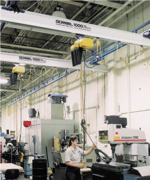
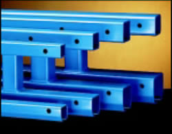
Rigid
Runways Provide for Superior
Positioning of Loads |
|
Calculating
Applied Forces to the
Supporting Structure |
|
|
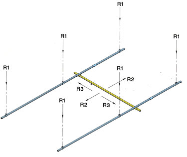
This
illustration shows the relative position and the
direction of forces that a ceiling-mounted bridge crane
applies to its supporting structure. Before installing any
crane system, it’s critical that you determine whether
your building will safely support the loads. |
|
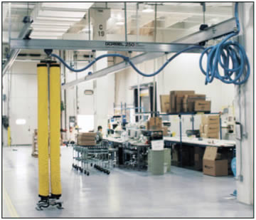
Work Station Bridge
Cranes are installed so that
the runways are rigid. They do not move laterally
or longitudinally. In addition, the floating end
trucks with horizontal wheels prevent binding. The
combination of these design features results in
unmatched ease of positioning and ease of movement.
The bridge travels smoothly down the runways, and
movement is unvarying along the way, no matter
where a load is positioned on the bridge. This allows
superior load positioning.
|
|
|
Loads
applied to the support structure can be
determined using the following formulas, where: |
|
|
|
|
|
|
|
 |
|
|
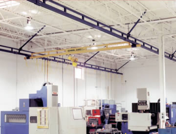
Another
advantage of rigid runways is that they can
be reinforced (trussed “S" series), so they are useful
where long spans are required. This eliminates the
need for expensive intermediate support stringers,
and it lowers overall installation cost. |
|
|
|
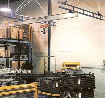
| Mixed
Capacity Bridge Crane Systems: |
|
|
|
Reduced
bridge dead weight equals better
ergonomic solutions. |
|
|
|
Mixed-capacity
systems allow multiple lower capacity
bridges to be used on higher capacity runways, provided
the equivalent center loads (ECL) are verified at the
factory to ensure that runways and hangers are not
overloaded. For example, using mixed-capacity end
trucks, four 500 lb. bridges (utilizing 500 series rail)
can be hung from a 2000 lb. runway, allowing side-by-
side use of all four bridges without overloading the
system. By mixing bridges of various sizes and capacities,
mixed-capacity systems offer reduced bridge
dead weight, easier movement, and reduced cost. |
|
|
|
|
|
|
|
|
R1
= vertical load applied by support hanger (lb.) |
|
R2
= longitudinal load applied by movement of the
crane to each runway (lb.) |
|
R3
= lateral force applied by movement of the trolley
and load to each runway (lb.) |
|
L1
= distance between support centers (ft.) |
|
|
(NOTE:
If there are only 2 supports/runway,
L1= L1 x 0.5) |
| What
is meant by Rated Capacity? |
|
|
|
The
rated capacity is the live load that can be lifted
by the crane system. The design load for the crane
system is based on the rated capacity plus 15% for
the weight of the hoist and trolley (capacity x 1.15)
and an additional 25% for impact (capacity x 1.25)
for a total design of capacity x 1.4 (Note, 25% impact
factor is good for hoist speeds up to 50 f.p.m.). For
example, a 1000 lb. Crane allows you to pick
up a 1000 lb. load, provided the hoist weighs 150 lb.
or less and the hoist speed is less than 50 feet per
minute. |
|
|
L4
= bridge span: center line distance between
runways (ft.) |
|
P
= live load capacity (lb.) |
|
1.4
= design factor (see description below) which
includes 25% for impact and 15% for assumed hoist
and trolley weight |
|
W
= weight per foot of runway (lb./ft.) See installation
guide below |
|
w
= weight per foot of bridge (lb./ft.) See installation
guide below |
|
R1
= 1.4 x P + (W x L1) + (w x L4) |
|
|
Design
load for deflection calculations is based on the
rated capacity plus 15% for the weight of the hoist and
trolley (capacity x 1.15). Under no conditions should the
crane be loaded beyond its rated capacity. Gorbel Work
Station Cranes meet or exceed the ANSI B30.11
specifications for underhung bridge cranes. |
|
|
|
|
|
2
|
|
|
R2
= ((1.15 x P) + (w x L4) )x .10 |
|
|
2
|
|
|
|
|
R3
= 1.15 x P x .20 |
|
|
|
|
|
|
|
WARNING:
Equipment described in this brochure is not
designed for, and should not be used for, lifting, supporting,
or transporting humans. Failure to comply with any one of the
limitations noted can result in serious bodily injury and/or
property damage. |
|
|
Pricing
and Dimensional Specifications -
Click a Load Capacity Link Here > |
|
|
|
|
|
|
|
|
|
|
| |
|
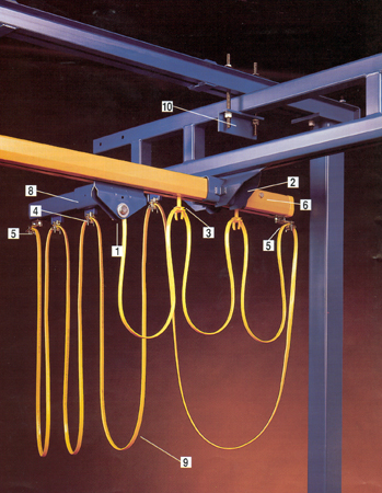
Anatomy
of a Work Station Crane
|
 |
|
|
 |
|
|
|
|
|
|
|
|
1 |
|
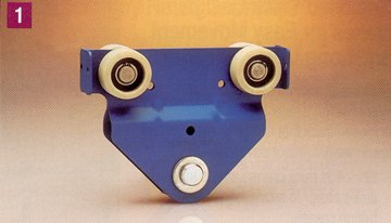
HOIST
TROLLEYS |
|
Hoist
trolleys provide the connection between the lifting
device and the monorail. The trolleys are designed for
effortless movement along the track. The stamped body
fits most rigid hook or eye lifting devices. |
|
|
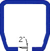
•
Wheels are tapered to match the 2° taper of the track.
This reduces rolling resistance and wheel
wear. Wheels
contain ball bearings that are sealed and
lubricated for
life.
• Trolleys are designed to operate in temperatures from
+5° F to +200° F.
• All trolleys meet or exceed the ANSI B30.11
specification for underhung bridge cranes. |
|
|
|
|
|
|
|
|
|
|
|
2
|
|
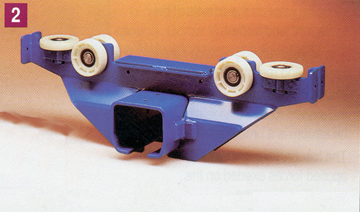
END
TRUCKS |
|
|
End
trucks provide the connection between the bridge
and runways. They are designed for effortless movement
along the runway.
• Wheels are tapered to match the 2° taper of the track,
which reduces rolling resistance and wheel wear.
Wheels contain ball bearings that are sealed and
lubricated for life.
• Two horizontal wheels center the end truck within the
runway which prevents binding of the bridge. As
a
result, the position of the load on the bridge
has little
effect on the amount of force needed to move the
bridge along the runway.
• Any slight runway track misalignment is taken up by the
bridge floating in one end truck, while the other
end
truck is firmly clamped to the bridge.
• All end trucks meet or exceed the ANSI B30.11
specification for underhung bridge cranes. |
 |
|
|
|
|
|
|
|
|
 |
|
|
|
|
|
3
|
|
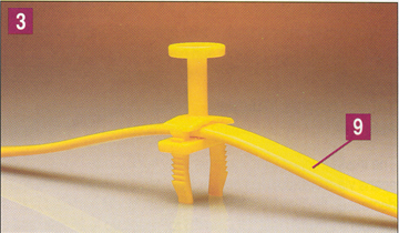
FESTOON
GLIDES |
|
Festoon
gliders are used to support flat cable along the
monorail, and they are standard on monorails of 63 feet
or less. No tools are required to attach the festooning to
the gliders. |
|
|
|
|
|
|
|
|
|
 |
|
|
|
|
|
4
|
|
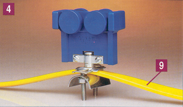
FESTOON
TROLLEYS |
|
Festoon
trolleys (optional) are used to support flat cable
or air hose along the monorail. The trolleys have four
wheels and a pivoting festoon saddle support. They are
ideally suited for long runways (greater than 63 feet) or
with round cable or air hose. With monorails greater than
63 feet or with an all aluminum system, festoon trolleys
are standard. Special festoon trolleys for vacuum hose
are also available. |
|
|
|
|
|
|
|
|
|
 |
|
|
|
|
|
|
5
|
|
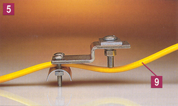
FESTOON
CLAMPS |
|
|
Festoon
clamps anchor the festooning at the start of the
monorail. They also prevent the festoon gliders from
exiting the track and they can provide a redundant stop
of the trolley. |
|
|
|
|
|
|
|
|
|
|
|
|
 |
|
|
|
|
|
|
6
|
|
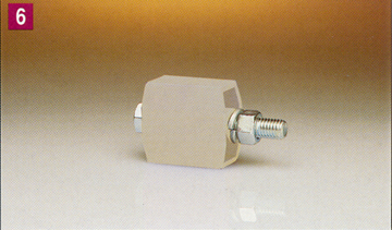
END
STOP BUMPERS |
|
|
High-impact
molded end stop bumpers are provided on
all monorails, to prevent the trolley from exiting the
track. The bumpers are bolted to the track to physically
limit the travel of the trolley. |
|
|
|
|
|
|
|
|
|
|
|
|
 |
|
|
|
|
|
7
|
|
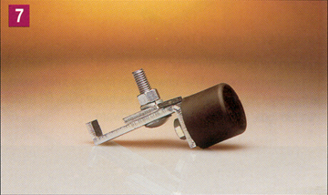
UNIVERSAL
BUMPERS |
|
A
universal bumper can be used as a secondary end
stop, either internally or externally. |
|
|
|
|
|
|
|
|
|
|
|
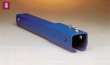
8
|
|
STACK
SECTIONS |
|
|
A
stack section at one end of a monorail serves as an
extension that allows festoon carriers to be stored on the
end of the monorail without reducing hoist coverage. |
 |
|
|
|
|
|
|
9
|
|
FLAT
CABLE AND/OR AIR HOSE |
|
A
flat cable festooning system is included in all
monorails. Plenty of cable is provided for 3 foot loops
on the monorail.
Optional air hose is also available and is supported by
optional festoon trolleys. |
|
|
|
|
|
Optional
air hose is also available and is supported by
optional festoon trolleys. Work Station Cranes can utilize
optional conductor bar electrification, but this results in
an increase up to 40% of the amount of effort required
to move the system. |
|
|
|
|
|
|
|
 |
|
10
|
|
HANGER
ASSEMBLIES |
|
Each
Work Station Bridge Crane or monorail is
provided with the number of standard hanger
assemblies listed, based on the maximum “L1” spacing
shown in this brochure. Sway bracing is required on all
systems, except flush-mounted systems. Sway bracing
kits are not included in the crane kit (see Sway Brace
Fitting caption on this page). |
|
|
|
|
|
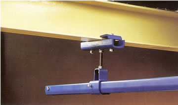
Standard
Hangers for Plain Steel Track |
|
Standard
hangers for plain steel track, with a 20 inch
threaded rod (B7 alloy), are included with each assembly.
The threaded rod can be field cut to custom lengths as
required. An optional 72 inch rod can also be supplied.
Two beam clips are bolted to the upper hanger bracket
and are clamped to the supporting structure. The upper
hanger brackets are adjustable for flange widths from
1 to 10 inches. |
|
Standard
Hanger - Plain Steel Track
|
|
|
|
 |
|
|
|
|
|
|
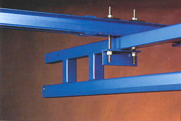
Hangers
for Trussed Steel Track
Hangers
for steel runways are included with each
assembly as shown. The runways are flush mounted
under the free standing support assemblies via spine
clamp angles, B7 alloy threaded rods, and the appropriate hardware. |
|
|
|
|
|
Standard
Hanger - Trussed Steel Track
|
|
|
|
|
|
|
|
|
|
 |
|
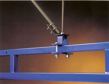
Sway
Bracing Fitting
(not supplied as standard) |
|
|
|
|
|
Sway
bracing is required on all systems except flush
mounted systems to provide for a rigid-mount runway
that allows the end truck to move freely. The fittings
permit easy sway bracing with 1 inch standard steel pipe
(pipe supplied by others). The flange is drilled to accept
a 5/8 inch bolt (bolt by others) with two U-bolts
(furnished). These optional fittings are not supplied
as standard with crane kits. |
|
|
|
|
|
Sway
Bracing Fitting
|
|
|
|
|
|
|
|
|
|
|
 |
|
|
|
|
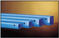
SPLICE
JOINTS FOR STEEL TRACK |
|
|
|
|
|
A
splice joint is used to join track sections together
and enable the installer to quickly and properly align
the joined sections of track. Adjusting bolts are
provided on the splice joint for leveling and aligning. |
|
|
|
| |
|
|
|
|
|
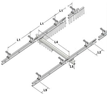
INSTALLATION
GUIDELINES
|
|
|
|
|
| Pricing
and Dimensional Specifications - Click a Load Capacity Link
Here |
|
|
|
|
|
CAPACITY |
SERIES |
WEIGHT
PER
FOOT |
MAX.
L1 |
MAX.
L2 |
MAX.
L5 |
MAX.
L9 |
250# |
GLC |
2.55 # |
6 |
8 |
18 |
18 |
|
GLCS |
4.88 # |
20 |
48 |
18 |
48 |
|
GLCSL |
8.14 # |
25 |
48 |
18 |
48 |
|
500# |
GLC |
4.11 # |
6 |
8 |
24 |
20 |
|
GLCS |
7.23 # |
20 |
48 |
24 |
48 |
|
GLCSL |
10.94 # |
25 |
48 |
24 |
48 |
|
GLCSLX |
11.26 # |
30 |
48 |
24 |
48 |
|
1000#
|
GLC |
6.50 # |
6 |
8 |
24 |
20 |
|
GLCS |
12.09 # |
20 |
48 |
24 |
48 |
|
GLCSL |
13.37 # |
25 |
48 |
24 |
48 |
|
GLCSLX |
15.31 # |
30 |
48 |
24 |
48 |
|
2000#
|
GLC |
9.00 # |
6 |
8 |
24 |
24 |
|
GLCS |
14.59 # |
20 |
48 |
24 |
48 |
|
GLCSL |
20.14 # |
25 |
48 |
24 |
48 |
|
GLCSLX |
20.95 # |
30 |
48 |
24 |
48 |
|
4000#
|
GLC |
9.00 # |
6 |
8 |
24 |
24 |
|
GLCS |
18.42 # |
20 |
48 |
24 |
48 |
|
GLCSL |
23.83 # |
25 |
48 |
24 |
48 |
|
GLCSLX |
28.02 # |
30 |
48 |
24 |
48 |
|
 |
|
|
|
|
L
1 = |
MAXIMUM
HANGER
CENTERLINE |
|
|
|
|
Maximum
Hanger Centerline is
considered from the center of a hanger
to the center of the neighboring
hanger. |
|
|
|
| Note: |
Anti-kick-up
end trucks* are required for the following:
bridges with < 8' span (L4) and a bridge
cantilever (L5) > 12"
bridges with < 10' span (L4) and a bridge
cantilever (L5) > 15"
bridges with < 15' span (L4) and a bridge
cantilever (L5) > 18" |
|
|
|
L
2 = |
SPLICE
JOINT CENTERLINE
TO HANGER CENTERLINE
Splice Joint Centerline to Hanger
Centerline is considered from
center of a splice joint to the center of
the nearest support hanger. |
|
|
|
|
|
|
|
|
|
|
|
|
|
|
|
|
L
5 = |
BRIDGE
CANTILEVER**
Bridge Cantilever is considered from
the centerline of the runway to the end
of the bridge (see table and notes). |
*
Anti-kick-up end trucks are not included as part
of the standard crane kits. |
|
|
|
|
|
|
|
|
|
|
|
|
|
**2000#
@ 10' span (L4) and bridge cantilever (L5)
15" need anti-kick-up end trucks.
Consult us for information on bridges
greater
than 15' span (L4). |
|
|
|
|
|
|
|
|
|
|
|
L
9 = |
MAXIMUM
RUNWAY
CANTILEVER
Runway Cantilever is considered from
the center of the end support assembly
to the end of the runway. |
|
|
|
|
|
|
|
|
|
|
|
|
STANDARD BRIDGE CANTILEVER
|
Bridge
Series |
Bridge Overall Length |
|
Steel |
|
<=23' |
28' |
29' |
33' |
34' |
| 250 |
12" |
18" |
24" |
NA |
NA |
| 500 |
12" |
18" |
24" |
18" |
24" |
| 1000 |
12" |
18" |
24" |
18" |
24" |
| 2000 |
12" |
18" |
24" |
18" |
24" |
| 4000 |
15" |
18" |
24" |
18" |
24" |
|
|
|
|
|
|
|
|
|
|
|
|
|
|
Note: |
Same
guidelines apply for Monorails
(GLMS,GLMSL,GLMSLX, ALM),
with the exception of the "L5" dimension
(not applicable). |
|
|
|
|
|
|
|
Note: |
Typical
L5 is 12". Max. L5 may not be
achievable (dependent on truss design
of bridge.) |
|
|
|
|
|
|
|
|
|
|
|
|
Bridge Cranes,
Cranes, Ceiling Mounted Bridge Cranes & Monorails, Enclosed
Track Design, Overhead Bridge Cranes, Hoist,
Top Running Bridge Cranes, and Under Running Crane from your
source for material handling equipment.
|
Back to Product Page
|